Better Vector – Better Correction
The transverse plane is the invasive plane on the human nervous system. This is evident by the orientation of the facets that restrict this motion below C2 to the ankles. The lumbar allow for strictly sagittal movement, the thoracic are coupled sagittal and frontal, and the cervical are as well sagittal/frontal primarily, with C1 the only true transverse capabilities.
These innate structural limitations exist to protect the housed nervous system.
This makes the accuracy to measure this plane vital. Currently the placement and analysis must be reconsidered for optimal results. That is the focus of this month’s discussion.
The vertex view, which measures the transverse plane, is the most difficult to position correctly and analyze with precision and accuracy. Keep in mind that without correcting this component, you are not correcting the misalignment.
A correction on the Nasium without a correction on the Vertex,
means your results are strictly positional
The present protocol to position and measure the vertex is in need of reconsideration. The analysis has been recently manipulated without a mathematical theorem. This is an issue for young practitioners who follow this non-science wisdom as protocol. Know that correcting the transverse plane is the essential component to decreased symptoms and increased correction stability. Positioning and analysis are the two functions of an accurate vertex.
Current positioning is skull based (chin cup). The overwhelming majority of all UCC use the mirror to place the skull on center without consideration of the rest of the body. The problem here is that this does not center all structures from a zero reference point. In other words, if the lower angle or the skull is off frontal, sagittal, or transverse plane, the atlas reacts to this position. This is the old discussion that if Bob lives 5 miles east from Sue and Sue lives 5 miles from north Larry, how far does Larry lives from Bob. There is no relative zero point.
The analysis is even more skewed with no mathematical foundation. It is currently measured from the center grid line as a relative zero point. The positioning assumes a perfect center reference line of misaligned structures. Yes, this analysis would work well if all structures were perfectly aligned as one structure. This does not exist on the misaligned pre film unless the practitioner jams the structures from chin cup to chair.
Questions
The questions I pose are:
- How do you position the vertex maintaining the integrity of the misalignment while removing the other distortion planes (neutralizing the planes)?
- How do you create a relative zero point to measure the true rotation where the lower angle and skull are measured from a zero axis (relative zero)?
Definitions
These questions give rise to two new definitions that elevate our ability to improve our position and analysis of a 3-D structure on a 2-D plane film.
Positioning while neutralizing planes and the measurement of a relative zero point in our analysis is another QSM3 point of interest:
- Neutralizing the planes: when taking a correct picture the plane being viewed must not be coupled with other planes. This creates a distortion of that plane. It must be removed or neutralized. In the vertex the frontal and sagittal must be neutralized.
- i.e., if the shoulders are twisted in the nasium film it will measure a larger lower angle than truly exists in the frontal plane. It must be removed.
- Relative zero: The geometrical reference point to measure from that allows you to determine the true deviation from zero.
i.e., 50 mph means 50 mph from zero
i.e., 50 mph from 30 mph means 20 mph
- By definition this is the intersection point of all planes or lines on the film
The New QSM³ Vertex Instrument
- Plane line (PL): the line though the primary ossification centers of the inferior aspects of the lateral masses
- Cervical Center Line (CCL): the line created by the bisection of C2-C7 using new vertex instrument
- Center skull line (CSL): the line created by the bisection of the skull using new vertex instrument
The QSM3 Vertex Placement
Requirements: 8 X 10 X-ray Cassette
Vertex Filter
Angle of the bucky @ 20 Degrees
The purpose of this film:
- Obtain an accurate view of atlas, the nasal septum and the C-2 spinal canal
- Neutralize the appropriate planes
- Determine the accurate degree of atlas rotation and the C-2 spinal canal rotation
- (neurological) from a zero reference point
Placement Sequence
- The chair must be parallel with the rails and centered on the center bucky.
- Set the bucky to 20 Degrees.
- Have patient sit centered in chair to minimize visual distortion
- Have patient lean forward and push back in chair. This sets the pelvic lever into extension, which mimics standing posture spinal lock. Have patient keep eyes open and seated in natural upright position (do not have the patient over extend out of basic neutral posture).
The following steps are how to build the proper vertex positioning from the pelvis upward. Do not use the mirror and just place the skull!
- Set center pelvis/ sacrum at center bucky by moving the chair right or left.
- Make sure the chair stays parallel to the bucky at all times. This with the patient’s buttocks completely against the back of the seat creates a neutral zero transverse and sagittal plane.
- From behind patient place your hands on the lateral aspects of shoulders and MOVE the fixed point (C7/T1) directly over mid sacrum. This is a key step in neutralizing the frontal plane.
- Place your hands on the skull of the patient and have the patient lift the chin into a comfortable extension. Do not force the patient into hyperextension. Any forced movement will create muscle distortion and change the misalignment and the ability to create relative zero.
- Place the chin in the cup using the wall-mounted mirror to guide you and then remove any lateral flexion gently using the mirror.
- With knees against the chair to stop chair rotation, remove all shoulder transverse/ sagittal distortion. This is the final key step of neutralizing the plane and relative zero. This now places the pelvis, shoulders, and skull parallel to bucky and fixed directly over mid-sacrum.
- The glabella must be on centered in the mirror.
- Final position is a pelvis up placement with pelvis under C7/T1, C7/T1 under glabella with the appropriate neutralizing of the planes and a relative zero position.
- Tube placement at center film through C1 and angle based on inferior occiput at appropriate line on bucky based on age and sex.
Final thoughts
- The mirror is only used as a check at the end. Building the placement from pelvis up will produce an accurate and precise picture
- If the glabella is off center at the end of the setup it is because of two possibilities:
First: The pelvis is off center of film. This is corrected by moving the pelvis back to center with the chair. The chair will be moved in the direction the glabella is off center.
Second: The pelvis is on center of film. This is corrected by pushing downward on the opposite shoulder with enough force to center glabella and bring neck on center.
QSM3 Vertex Measurement
The purpose of the new QSM3 Vertex Measurement is to accurately establish the bisection of the PL, CCL, and CSL. The bisection point is the zero point and is where the practioner places the zero point of the protractor.
Vertex Scope procedure
- Mark the lateral aspects of C2 and C7
- Using the vertex scope to find the cervical center line (CCL) and score a ½” line at the neural ring.
- Strike a ½” dash at the inferior aspects of each lateral mass (primary ossification). Strike a line connecting the two dashes. This is the plane line (PL)
- The intersection of the PL and CCL is the relative zero point (RZP)
- Bisect the line of raphe using the vertex scope
- Measure the rotation by placing the zero point of the vertex scope at the relative zero point (RZP) and measure the rotation off vertical of the line of the line of raphe.
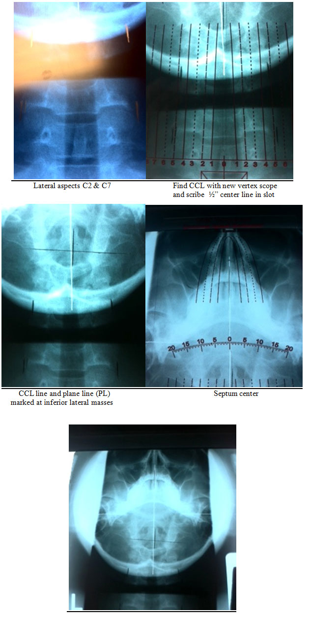
The protractor is placed at the intersection of the PL and CCL. This is the geometric relative zero point (RZP). Notice that it runs parallel to the lower angle and is off center of the dens and grid line, which will read differently from the current and older vertex analyses. Measure from RZP to septum center (CSL)
Final Discussion
As always, my door is open to help and to discuss your thoughts and wisdoms. The best way to connect is to put your thoughts in an email. Please include your cell and a good time for me to talk. I am in process of building a web with a doctor’s blog.
As far as the article goes, start to re-ex the vertex and to calculate the rotation with the new analysis. It will help. Remember, the vertex is the key to the spinous and the lower angle correction. I Re-vertex 10 to 1 vs. the nasium.
Russell Friedman DC
January 4, 2011