The Hyperbolic Arc of the Frontal Plane
Further Discussion on Static and Dynamic Aspects
The goal of any vector-based procedure is to first calculate the correction vector and then to access the reduction pathway. This is a two-part process. First, to establish the vector and second, to know where to apply it to access the reduction pathways. The correction vector alone (the static aspect) cannot access the correct reduction pathway autonomously. It needs to be applied at the access point or entrance to the reduction pathway and then routed through the collective vertebrae. This entrance point is conceived by understanding the relationship of the upper cervical x-ray series and the Anatometer measurements of the pelvis below.
This top-to-bottom “mapping” of the closed kinetic chain gives the doctor the entrance placement for the skull and headpiece. It then presets a closed contact path or connection to allow the vector to travel down the appropriate resistant pathway.
The Static Aspect encompasses:
- Machine balance, port, and filters
- Precision and accuracy of analysis
- Anatometer
- Leg Check
From the above information, the pathway of the vector from the three structures (skull, atlas, and lower section C2 – Pelvis) can be measured, mapped, and accessed.
This is the integral step to access the reduction pathway so the vector can overcome the resistance. This is the dynamic aspect of the correction process.
To take this step, the Anatometer measurements are recorded (weight differential, pelvic rotation, and fixed point) and the QSM3 algorithm then details this placement. This is accomplished by aligning the structures into the resistant pathway so the force travels up or down through it. The atlas (C1), because of its two-cup (coupling) design, can be used to direct the vector force through skull, headpiece, and pelvic 3D placement. It is this protocol that establishes a specific placement protocol.
Every misalignment has multiple pathways. Each pathway has a placement that is required to be changed to access and then reduce it. It’s like a game of golf… hit the ball re-assess, hit it again, re-assess, and hit it again, etc., until you reach maximum available correction. This is a ONE VECTOR MULTIPLE PLACEMENT PROTOCOL. This game of correction is so much more difficult without the tools to identify the pathway and its access or entrance point.
I have found that there is more than one placement that corrects a misalignment correctly unless you use enough force to jam it to a FALSE zero. A false zero will always show a short leg on one side and an Anatometer weight differential on the opposite side.
Here are the questions that initiated this search:
- Do you understand the breakdown pathway of the misalignment (head to toe) before, during, or after you initiate the dynamic correction process?
- Do you have comprehensive system (algorithm) to correct each pre and subsequent post?
- Do you know what to do on each post?
- Do you feel your knowledge base is complete?
The dynamic aspect of the QSM3 algorithm begins to address these questions. Like any successful science, it will continue to grow. It is apparent that there are many factors involved in spinal breakdown and its correction. D.D. Palmer said “mechanical stress, toxins, and auto-suggestion disrupts our tone.” But innovation converts to better possibilities in the “dynamic aspect” of spinal corrections.
Though still incomplete, the QSM³ protocol moves the “mechanical stress” aspect forward by systematically accounting for the variable possible resistances (dynamics) caudal to the cervical spine.
The Dynamic Aspect encompasses:
The Dynamic aspect of the correction first:
- Measures three-dimensional pathways
- Accesses the pathways through placement, doctor position
Then the doctor, through position, use of the wrist lever, and torque can change the direction of the vector to:
- Change the frontal plane direction
- Change the rotation direction
- Access multiple pathways
Understanding all of these above concepts well enough to use them in practice, requires a series of sequential classes that are now offered three times a year (QSM3)
The focus of this article is to discuss the frontal plane aspect of the correction and its access points. The stabilizing factor in a misalignment is the frontal plane. The symptom aspect of the misalignment is the rotation.
This means if you do not get the frontal plane on vertical it will be unstable and if you do not clear the rotation the patient will be unhappy.
Frontal Plane Access Points
The frontal plane is the easiest plane to correct. Yet, at times it can be difficult for four reasons:
- You are not accessing all the frontal plane access (entry) pathways
- Resolution: roll the skull (see below)
- You are on the wrong side of laterality
- Reanalyze: check skull asymmetry and C1 upper and lower registry points
- Torque issue
- Anterior torque corrects the frontal plane towards vertical (Remember: use only if measured anterior from pelvis)
- Height to rotation is below 45-degrees
- When the height is less than rotation, the frontal plane pathway has to be accessed though increasing headpiece tilt
Case Study
The case I would like to discuss today addresses the accessing of the multiple frontal pathways.
The lateral view of the base of support is an asymmetrical hyperbolic curve.
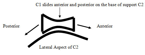
The C1 and skull ROLLS on this sagittal arc (depicted above). It’s through this plane that the frontal plane misalignment is entered or accessed. Rolling the skull in multiple positions (chin tuck to extension) will access these pathways.
I have found that if the rotation clears, and the patient does not come to vertical, then there is more than one frontal plane resistant pathway. This protocol is appropriate to further the result.
Protocol
The protocol is to systematically move the skull to three positions:
- First set the skull into flexion (chin tuck)
- Second to patient neutral
- Third to extension (chin up).
At each position, check the pathway for resistance.
This will make available these additional entrance points and facilitate the access of frontal pathways to correct the patient to vertical and create spinal stability.
Case Study #1
Patient: Andrea H
Symptomatic Picture: MS
QSM3 Simple Frontal
Anatometer: Wt Right 16.6lbs pelvis posterior 3
AT: L1 Pl +1
OD: L1 At/OD 0
BC: L1 C/A +3 1/2
SP: L2 < +1/4
Vector: I 2 LH4 3/4 P1/2
U
Discussion:
- The weight scales are opposite laterality, so the force must be redirected to the right side to travel R to L to correct the pathway to vertical.
- The rotation of the atlas is left posterior, but the pelvis is right posterior. The rotation vector also must be reversed to correct the posterior pelvic pathway.
Vector Issue:
- Vector needs to be redirected right to left, based on the weight scales.
- The vector has more frontal action (height larger than C/A and above rotation [above 45°])
Patient Placement – First Correction:
Hdpc: Tilt down to redirect force to go R to L (weight)
Skull: Chin up to direct force P to A on the weighted side
Pelvis: Left pelvis tractioned A to P to preset the pathway
Shoulder: Left shoulder A to P or right shoulder P to A
First Post:
Good reduction on film but patient did not come to vertical on the anatometer
Anatometer: R6lbsP-1
Reposition on Post Based on the New Anatometer Readings:
Goal: To clear second frontal pathway of R6lbs
Checked chin in Neutral and Flexion
Result: Anatometer L1.8P1
Case Study #2
Patient: Trey K
Symptomatic Picture: MS
QSM3 Simple Frontal
Anatometer: Wt Right 28.7 Pelvis anterior 1mm
AT: R1 Pl +1
OD: R1 At/OD 0
BC: R1 C/A +1 1/2
SP: R1/2 < -1
Vector: I 2 RH1A2 1/2
U
Discussion:
This is a large frontal component pathway with no rotational component that may fool you and blow out the pelvis because it is jammed in. Don’t panic …just stay with it and follow the algorithm
Vector Issue:
- Height is smaller than Rotation (below the 45°). This creates more
transverse action than frontal action
Placement:
Hdpc: Tilt up to direct force to go R to L (weight)
Skull: Chin tuck to direct force A to P
Pelvis: Right pelvis tractioned A to P and s to I
Shoulder: Right side A to P
Post:
Patient did not come to vertical
Anatometer: R22.2A0
Reposition on post Anatometer:
(Because patient did not come to vertical)
Goal: To clear 2nd frontal pathway of R22.2lbs
Checked chin in Neutral and Extension: There was a second pathway in extension (S to I)
Result: Anatometer L5P1
Happy hunting!
Russell Friedman, DC
September 1, 2010